creo sheet metal drawing pdf Ensure you have the sheetmetal module attached to your license of Pro/ENGINEER before beginning. 1. Create a part (sub-type sheetmetal) with extruded wall as first feature; sketch as . Upgrade your CNC router with a vacuum table for efficient and precise machining. Learn how to build your own DIY setup with our step-by-step guide. Try it now!
0 · sheet metal creo parametric
1 · flat pattern sheet metal drawing
2 · creo sheet metal tutorial PDF
3 · creo sheet metal tutorial
4 · creo sheet metal practice drawing
5 · creo sheet metal basics
6 · creo practice sheet metal models
7 · creo parametric sheet metal tutorial
Metal boxes must be used with metallic cables or conduit. Answers based on the National Electrical Code. Local amendments may apply. Check with your local building officials. Remember Junction boxes have to be accessible. Under the insulation is not acceptable. Metal boxes are better when you need the strength and volume to make up a ton of wires.Use a metal electrical box when metal-sheathed cable (also called armored BX cable) or metal conduit runs in or out of the box. Metal cable and conduit depend on the contact from its metal sheathing to the metal box to complete grounding.
Ensure you have the sheetmetal module attached to your license of Pro/ENGINEER before beginning. 1. Create a part (sub-type sheetmetal) with extruded wall as first feature; sketch as . Creo Parametric: Creation of a simple part and flat pattern in the Sheet Metal module (2) This method of working with sheet metal is to create the model within sheet metal . Creo Parametric: Creation of a simple part and flat pattern in the Sheet Metal module (1) Level: basic, Year 10/11 Contribution to D&T, Maths, Science: design and creation .
Creotm Parametric to create, view, and annotate models and drawings. Detailed Drawings support additional view types and multisheets, offers numerous commands for manipulating .
In Creo Parametric, the parametric part modeling process involves the following steps: 1. Set up Units and Basic Datum Geometry. 2. Determine the type of the base feature, the first solid feature, of the design. Note that Extrude, Revolve, .Every sheet metal design starts with the decision for a certain manufacturing shop and a specific material. Then you go on with creating a basic sheet metal part. You must first use a workplane and create the 2D geometry which defines the .This training course enables you to use your introductory modeling skills to create sheet metal models, including walls, bends, notches, and form features. On completion of this course, you .
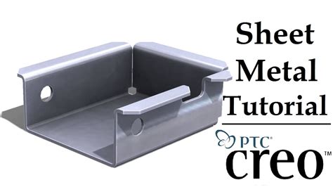
This document provides an overview of a training course on sheetmetal design using Creo Parametric. The course objectives are to teach students how to create primary and secondary sheetmetal walls, apply various features, generate flat .SheetmetalusingCreoParametric4.0 Overview CourseCode TRN-5107-T CourseLength 16Hours Inthiscourse,youwilllearnhowtocreate sheetmetalpartsinCreoParametric.TheTo create a sheet metal part in Pro/E, choose Sheetmetal instead of selecting Solid from the New (file) dialog. The FEAT CLASS menu structure appears differently in Pro/SHEETMETAL mode. protrusion. After constructing the first Wall feature, you may create surface or solid features, as well as datum or sheet metal features.Ensure you have the sheetmetal module attached to your license of Pro/ENGINEER before beginning. 1. Create a part (sub-type sheetmetal) with extruded wall as first feature; sketch as in following figure: FEATURE / CREATE / WALL / EXTRUDED / DONE / ONE SIDE / DONE / select your planes etc.
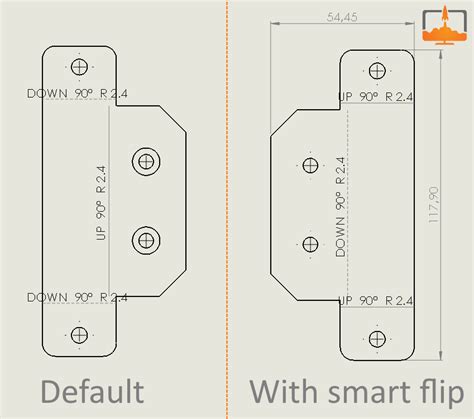
Creo Parametric: Creation of a simple part and flat pattern in the Sheet Metal module (2) This method of working with sheet metal is to create the model within sheet metal from a number of flat pieces joined together. The alternative is to create a solid first then shell it before opening the sheet metal module. Create and name a new Sheetmetal .
sheet metal creo parametric

Creo Parametric: Creation of a simple part and flat pattern in the Sheet Metal module (1) Level: basic, Year 10/11 Contribution to D&T, Maths, Science: design and creation of nets for construction of containers, nets of geometrical shapes. This method of working with sheet metal is to create a solid first thenCreotm Parametric to create, view, and annotate models and drawings. Detailed Drawings support additional view types and multisheets, offers numerous commands for manipulating items in a drawing, and lets you add and modify different
how to hang window boxes on steel siding
In Creo Parametric, the parametric part modeling process involves the following steps: 1. Set up Units and Basic Datum Geometry. 2. Determine the type of the base feature, the first solid feature, of the design. Note that Extrude, Revolve, or Sweep operations are the most common types of base features. 3.Every sheet metal design starts with the decision for a certain manufacturing shop and a specific material. Then you go on with creating a basic sheet metal part. You must first use a workplane and create the 2D geometry which defines the exact contours of the new basic sheet.This training course enables you to use your introductory modeling skills to create sheet metal models, including walls, bends, notches, and form features. On completion of this course, you will have acquired the skills to confidently manipulate sheet metal geometry, adjust bend developed lengths, and convert solid parts.
This document provides an overview of a training course on sheetmetal design using Creo Parametric. The course objectives are to teach students how to create primary and secondary sheetmetal walls, apply various features, generate flat patterns, and create detailed drawings.SheetmetalusingCreoParametric4.0 Overview CourseCode TRN-5107-T CourseLength 16Hours Inthiscourse,youwilllearnhowtocreate sheetmetalpartsinCreoParametric.TheTo create a sheet metal part in Pro/E, choose Sheetmetal instead of selecting Solid from the New (file) dialog. The FEAT CLASS menu structure appears differently in Pro/SHEETMETAL mode. protrusion. After constructing the first Wall feature, you may create surface or solid features, as well as datum or sheet metal features.
flat pattern sheet metal drawing
Ensure you have the sheetmetal module attached to your license of Pro/ENGINEER before beginning. 1. Create a part (sub-type sheetmetal) with extruded wall as first feature; sketch as in following figure: FEATURE / CREATE / WALL / EXTRUDED / DONE / ONE SIDE / DONE / select your planes etc. Creo Parametric: Creation of a simple part and flat pattern in the Sheet Metal module (2) This method of working with sheet metal is to create the model within sheet metal from a number of flat pieces joined together. The alternative is to create a solid first then shell it before opening the sheet metal module. Create and name a new Sheetmetal .
Creo Parametric: Creation of a simple part and flat pattern in the Sheet Metal module (1) Level: basic, Year 10/11 Contribution to D&T, Maths, Science: design and creation of nets for construction of containers, nets of geometrical shapes. This method of working with sheet metal is to create a solid first thenCreotm Parametric to create, view, and annotate models and drawings. Detailed Drawings support additional view types and multisheets, offers numerous commands for manipulating items in a drawing, and lets you add and modify different
In Creo Parametric, the parametric part modeling process involves the following steps: 1. Set up Units and Basic Datum Geometry. 2. Determine the type of the base feature, the first solid feature, of the design. Note that Extrude, Revolve, or Sweep operations are the most common types of base features. 3.
Every sheet metal design starts with the decision for a certain manufacturing shop and a specific material. Then you go on with creating a basic sheet metal part. You must first use a workplane and create the 2D geometry which defines the exact contours of the new basic sheet.This training course enables you to use your introductory modeling skills to create sheet metal models, including walls, bends, notches, and form features. On completion of this course, you will have acquired the skills to confidently manipulate sheet metal geometry, adjust bend developed lengths, and convert solid parts.

This document provides an overview of a training course on sheetmetal design using Creo Parametric. The course objectives are to teach students how to create primary and secondary sheetmetal walls, apply various features, generate flat patterns, and create detailed drawings.
creo sheet metal tutorial PDF


how to hard wire into electrical box
how to hide electrical box in front yard
Metal boxes are used for metal conduit or armored (BX) cable installations. They provide excellent durability and grounding capabilities. Plastic boxes are more commonly used with non-metallic sheathed cables and offer benefits such as lightweight construction and resistance to corrosion.
creo sheet metal drawing pdf|creo sheet metal basics