creo sheet metal basics PTC Creo Parametric 9.0 Basic Sheet Metal Tutorial For Beginner. This tutorial is designed for beginners who have basic knowledge of PTC Creo Parametric 9.0.. Power Inlet 50 Amp Twist Lock Nema 3R. SKU: #PB50; #GNRC50; #PBN50; Max. Generator Running Watts 12500; Max. Generator Input 50A@125/250VAC; Cabinet Type, NEMA Outdoor, NEMA 3R; NEMA Configuration CS6375; Connector Required CS6364
0 · sheet metal in creo parametric
1 · sheet metal design in creo
2 · sheet metal creo tutorial
3 · flat vs flange in creo
4 · creo sheet metal tutorial pdf
5 · creo sheet metal practice drawing
6 · creo parametric sheet metal tutorial
7 · creo convert to sheet metal
Find Metal 2-Gang electrical boxes at Lowe's today. Shop electrical boxes and a variety of electrical products online at Lowes.com.
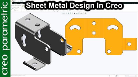
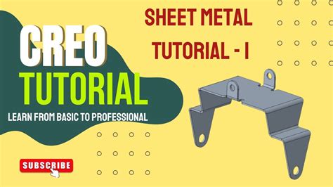
In this tutorial, you will learn a step-by-step approach to designing a sheet metal part in Creo Parametric. The tutorial covers the planar wall, extrude wall, flat wall, and flange wall. PTC Creo Parametric 9.0 Basic Sheet Metal Tutorial For Beginner. This tutorial is designed for beginners who have basic knowledge of PTC Creo Parametric 9.0..Sheet metal parts are solid models that can be represented in either sheet metal form or as a flat model. These parts are of uniform thickness and can be modified by adding features. Features . In this tutorial, we will learn about the basic techniques related to ‘Sheet Metal’ functionality of ‘Creo Parametric’ by modelling a Cover. In the creation .
Learn how to use Creo Parametric 10.0 to manipulate sheet metal geometry, adjust bend developed lengths, and convert solid parts. Check out this video on Creo Sheetmetal Design from PTC Application Engineers Presenters: Lino Tozzi (Technical Specialist, Fellow) and Ryan Butcher
1: Introduction to the Creo Parametric Sheetmetal Design Process. 2: Sheetmetal Model Fundamentals. 3: Creating Primary Sheetmetal Wall Features. 4: Creating Secondary .Every sheet metal design starts with the decision for a certain manufacturing shop and a specific material. Then you go on with creating a basic sheet metal part. You must first use a workplane and create the 2D geometry which defines the .

In this tutorial, you will learn a step-by-step approach to designing a sheet metal part in Creo Parametric. The tutorial covers the planar wall, extrude wall, flat wall, and flange wall.Creo Elements/Direct Sheet Metal can generate an accurate 2D drawing of a flattened (unfolded) sheet metal part. With a single command, Creo Elements/Direct Sheet Metal generates the flat . In this tutorial, you will learn a step-by-step approach to designing a sheet metal part in Creo Parametric. The tutorial covers the planar wall, extrude wall, flat wall, and flange wall.
PTC Creo Parametric 9.0 Basic Sheet Metal Tutorial For Beginner. This tutorial is designed for beginners who have basic knowledge of PTC Creo Parametric 9.0..Sheet metal parts are solid models that can be represented in either sheet metal form or as a flat model. These parts are of uniform thickness and can be modified by adding features. Features include walls, cuts, rips, bends, unbends, bend backs, forms, notches, punches, and relief. In this tutorial, we will learn about the basic techniques related to ‘Sheet Metal’ functionality of ‘Creo Parametric’ by modelling a Cover. In the creation .
Learn how to use Creo Parametric 10.0 to manipulate sheet metal geometry, adjust bend developed lengths, and convert solid parts. Check out this video on Creo Sheetmetal Design from PTC Application Engineers Presenters: Lino Tozzi (Technical Specialist, Fellow) and Ryan Butcher

1: Introduction to the Creo Parametric Sheetmetal Design Process. 2: Sheetmetal Model Fundamentals. 3: Creating Primary Sheetmetal Wall Features. 4: Creating Secondary Sheetmetal Wall Features. 5: Bending and Unbending Sheetmetal Models. 6: Modifying Sheetmetal Models. 7: Sheetmetal Setup and Tools. 8: Detailing Sheetmetal Designs
Every sheet metal design starts with the decision for a certain manufacturing shop and a specific material. Then you go on with creating a basic sheet metal part. You must first use a workplane and create the 2D geometry which defines the exact contours of the new basic sheet.In this tutorial, you will learn a step-by-step approach to designing a sheet metal part in Creo Parametric. The tutorial covers the planar wall, extrude wall, flat wall, and flange wall.Creo Elements/Direct Sheet Metal can generate an accurate 2D drawing of a flattened (unfolded) sheet metal part. With a single command, Creo Elements/Direct Sheet Metal generates the flat directly from the 3D model.
sheet metal in creo parametric
In this tutorial, you will learn a step-by-step approach to designing a sheet metal part in Creo Parametric. The tutorial covers the planar wall, extrude wall, flat wall, and flange wall.
PTC Creo Parametric 9.0 Basic Sheet Metal Tutorial For Beginner. This tutorial is designed for beginners who have basic knowledge of PTC Creo Parametric 9.0..Sheet metal parts are solid models that can be represented in either sheet metal form or as a flat model. These parts are of uniform thickness and can be modified by adding features. Features include walls, cuts, rips, bends, unbends, bend backs, forms, notches, punches, and relief. In this tutorial, we will learn about the basic techniques related to ‘Sheet Metal’ functionality of ‘Creo Parametric’ by modelling a Cover. In the creation .
Learn how to use Creo Parametric 10.0 to manipulate sheet metal geometry, adjust bend developed lengths, and convert solid parts.
Check out this video on Creo Sheetmetal Design from PTC Application Engineers Presenters: Lino Tozzi (Technical Specialist, Fellow) and Ryan Butcher1: Introduction to the Creo Parametric Sheetmetal Design Process. 2: Sheetmetal Model Fundamentals. 3: Creating Primary Sheetmetal Wall Features. 4: Creating Secondary Sheetmetal Wall Features. 5: Bending and Unbending Sheetmetal Models. 6: Modifying Sheetmetal Models. 7: Sheetmetal Setup and Tools. 8: Detailing Sheetmetal DesignsEvery sheet metal design starts with the decision for a certain manufacturing shop and a specific material. Then you go on with creating a basic sheet metal part. You must first use a workplane and create the 2D geometry which defines the exact contours of the new basic sheet.In this tutorial, you will learn a step-by-step approach to designing a sheet metal part in Creo Parametric. The tutorial covers the planar wall, extrude wall, flat wall, and flange wall.
sheet metal design in creo

Get ready for a wild ride with this Twisted Metal game for Sony PlayStation 1. This action-packed game is sure to keep you on the edge of your seat as you navigate through the levels. With a T-Teen rating, it's suitable for most players, and the game's publisher, Sony, has done an excellent job of bringing the game to life.
creo sheet metal basics|sheet metal creo tutorial