sheet metal cross break angle A Cross Break in sheet metal is when multiple obtuse Bend Angles of approximately 170° are made across a flat section thin metal. Cross breaks are most commonly in an X shape, forming a slight pyramid shape in the metal . Outdoor electrical junction boxes are designed to keep sensitive electrical connections protected and secure in any environment, even underground. Meeting a variety of NEMA and IP ratings ensures our waterproof junction boxes are robust and durable for outdoor use, but they can also be used for indoor applications.
0 · solidworks edge cross break
1 · solidworks cross break tool
2 · solidworks cross break template
3 · solidworks cross break layout
4 · solidworks cross break instructions
5 · solidworks cross break chart
6 · solidworks cross break
7 · sheet metal cross breaks
Tamper-resistant junction box for UniFi Bullet, Dome, and Turret cameras that enhances mounting durability, aesthetics, and ease of maintenance. Supports flat surface, pole and pendant mounting Includes side and rear 3/4" conduit entrances
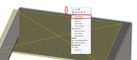
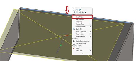
You can edit the cross break sketch to move corners and change relationships. When you create a drawing of a sheet metal part with a cross break, the flattened view is labeled with the bend direction, bend radius, and bend angle.A Cross Break in sheet metal is when multiple obtuse Bend Angles of approximately 170° are made across a flat section thin metal. Cross breaks are most commonly in an X shape, forming a slight pyramid shape in the metal . Measure angle between faces. If you’ve done this correctly, the faces should be split and you should be able to measure an angle between the faces. The SOLIDWORKS .Click Cross Break (Sheet Metal toolbar) or Insert > Sheet Metal > Cross Break. In the PropertyManager, select: The face on which to create the cross break; The direction of the .
A cross break is simply a diagonal bend (very slight bend) from two corners of a part. They are typically used on relatively large flat ares to keep the panel from bowing easily. .Making a cross break. - [Instructor] A cross break allows you to stiffen a flat surface in a sheet metal part, and it's used extensively in HVAC panels or anytime you see a big flat.
The cross break command lets you insert a graphical representation of a cross break in a sheet metal part. The cross break is not a geometric entity and it does not alter the geometry of the.Click Cross Break (Sheet Metal toolbar) or Insert > Sheet Metal > Cross Break. In the PropertyManager, select: The face on which to create the cross break; The direction of the cross break; The Break Radius; The Break Angle; Click .

po box 2247 caulfield junction victoria
"Most design softwares with respectable sheet metal packages will have a specific Cross Break function." Creo is more of a solid modeler than a sheet-metal package. The reason is that there are too many tweaks in sheet .Click Cross Break (Sheet Metal toolbar) or Insert > Sheet Metal > Cross Break. In the PropertyManager, select: The face on which to create the cross break; The direction of the cross break; The Break Radius; The Break Angle; Click .Click Cross Break (Sheet Metal toolbar), or Insert > Sheet Metal > Cross Break. Faces: Face on which the cross break is inserted. Reverse Direction: . Angle to be used to create the cross break. Parent topicCross Breaks. Adding a Cross Break. Displaying the Cross Break Parameters in . Cross Break Option Cross breaks are a cost effective method for strengthening a thin piece of sheet metal. Typically, this is done in an X shape, however two lines crossing at most angles will add strength.
In HVAC or duct work design, cross breaks are used to stiffen sheet metal. The Cross Break command lets you insert a graphical representation of a cross break in a sheet metal part. . bend radius, and bend angle. Adding a Cross Break; Modifying a Cross Break Sketch You can edit a cross break sketch to move the points that define the sketch.Adding a Cross Break. Displaying the Cross Break Parameters in a Drawing. When you create a part with a cross break, the flattened view is labeled with the bend direction, bend radius, and bend angle. Modifying a Cross Break Sketch. You can edit a cross break sketch to move the points that define the sketch. Cross Break PropertyManagerI mean you can remove the metal in the score with thousands of different tools. Shaper, files, dremel, hacksaw. Back of file, graver, You can use the edge of the angle iron as a creasing stake. Or the edge of a metal table.Click Cross Break (Sheet Metal toolbar) or Insert > Sheet Metal > Cross Break. In the PropertyManager, select: The face on which to create the cross break; The direction of the cross break; The Break Radius; The Break Angle; Click .
Click Cross Break (Sheet Metal toolbar), or Insert > Sheet Metal > Cross Break. Faces: Face on which the cross break is inserted. Reverse Direction: . Angle to be used to create the cross break. Parent topicCross Breaks. Adding a Cross Break. Displaying the Cross Break Parameters in .
Click Cross Break (Sheet Metal toolbar) or Insert > Sheet Metal > Cross Break. In the PropertyManager, select: The face on which to create the cross break; The direction of the cross break; The Break Radius; The Break Angle; Click .
Radius and bend deduction numbers can be entered into the sheet metal feature in Solidworks so your flat patterns actually work out. . they also are not usually two 90deg bends. the middle bit ends up being laid over at an angle a bit. . He got a talking to about "proper cross-departmental communication", but yeah was pretty damned funny .Measure angle between faces. A press brake makes bends up to 90°. . Click Cross Break (Sheet Metal toolbar), or Insert > Sheet Metal > Cross Break. Cincinnati – 230 Ton Hydraulic – 14′ bed, 12′-6″ between frame.159 SolidWorks Sheet Metal Tutorial: Cross-Break, reasons to use, real examples, single and multiple faces, cross break .Click Cross Break (Sheet Metal toolbar), or Insert > Sheet Metal > Cross Break. Faces: Face on which the cross break is inserted. . Angle to be used to create the cross break. Parent topic Cross Breaks. Related tasks. Adding a Cross Break. .300 S Pennell Rd, Suite 100, Media, PA 19063. 610-484-4161. [email protected]
The dimensions of a part with a cross break are not changed. You can edit the cross break sketch to move corners and change relationships. When you create a drawing of a sheet metal part with a cross break, the flattened view is labeled with the bend direction, bend radius, and bend angle.
300 S Pennell Rd, Suite 100, Media, PA 19063. 610-484-4161. [email protected] Add a note to define the bend angle of the cross break How to create a sheetmetal cross break in Fusion. Autodesk Support. Aug 20, 2024. Products and versions covered. Issue: How to create a sheetmetal cross break in Fusion. Solution: A sheetmetal cross break could be added in the Drawing workspace or the Design workspace using the methods .Click Cross Break (Sheet Metal toolbar), or Insert > Sheet Metal > Cross Break. Faces: Face on which the cross break is inserted. . Break Angle: Angle to be used to create the cross break. Parent topicCross Breaks. Adding a Cross Break. Displaying the Cross Break Parameters in .
A tool for bending sheet metal and in particular for making bends along the edges and a bend known as a cross break for duct work. A pair of longitudinal right angle members are spaced apart at each end and welded together forming a gap through which a piece of sheet metal is inserted. A pair of parallel rods are welded one to each one of the coplanar webs and perpendicular to .
Adding a Cross Break. Displaying the Cross Break Parameters in a Drawing. When you create a part with a cross break, the flattened view is labeled with the bend direction, bend radius, and bend angle. Modifying a Cross Break Sketch. You can edit a cross break sketch to move the points that define the sketch. Cross Break PropertyManager Only a few degrees of bending angle are needed, because the cross-break pattern allows thin panels to stay relatively flat but still benefit from the increased rigidity that bending (tensioning) the sheet provides. . Sheet metal is a versatile material with a huge variety of applications that is matched only by the diversity of different .
Click Cross Break (Sheet Metal toolbar) or Insert > Sheet Metal > Cross Break. In the PropertyManager, select: The face on which to create the cross break; The direction of the cross break; The Break Radius; The Break Angle; Click .' 2. Iterates over all features in the part and gets the ' cross break feature. ' 3. Names the cross break feature's face. ' 4. Prints to the Immediate window this cross break ' feature data: ' * Name of the face ' * Whether its direction is reversed ' * Radius ' * Angle ' . To you sheet metal guys. is 11GA 304 stainless steel too thick to try to form a cross-break? It is a rectangular sheet, about 12" x 16". This is a bottom panel of a box.
Cross breaks are a cost effective method for strengthening a thin piece of sheet metal. Typically, this is done in an X shape, however two lines crossing at most angles will add strength. This section contains the following topics:
When you create a part with a cross break, the flattened view is labeled with the bend direction, bend radius, and bend angle. To display the cross break parameters in a drawing: Click Make Drawing from Part/Assembly (Standard toolbar) or File > Make Drawing from Part .
solidworks edge cross break

Send me exclusive offers, unique gift ideas, and personalized tips for shopping and selling on Etsy. Etsy is powered by 100% renewable electricity. Cool vintage metal Wilco cash box by Union Steel LeRoy NY. Lots of scratching, discolorations, paint wear and rust (see photos).
sheet metal cross break angle|solidworks cross break instructions